1. Attach your requirements
Choose your industry and assessment type on Evaluations. Upload up to three PDF or Excel (.xlsx or .xls) documents, up to 5 MB each. Available for every industry and sector.
Review visible building-construction conditions, match findings to selected-state and local adopted requirements, and keep project photos with detailed corrective-work reports.
Illustrative image and finding; not a live assessment or compliance result.
Upload customer directions, guidelines, standards or contract requirements as PDF or Excel files. TruInspector Ai uses the relevant requirements alongside your photos and recorded videos to support a focused assessment.
Choose your industry and assessment type on Evaluations. Upload up to three PDF or Excel (.xlsx or .xls) documents, up to 5 MB each. Available for every industry and sector.
Identify the site, location and relevant area. Add photos or recorded video, select the assessment type, and attach your requirements for any specific priorities.
Relevant findings identify the customer document and available page, section or worksheet reference, explain the visible concern, and list corrective actions and missing field checks. Download the report as PDF or Excel.
Customer requirements are identified separately from official regulations. Confirm the applicable edition and scope; an upload does not establish legal applicability or certify compliance. Attachments stay within your signed-in workspace and are not included in public picture links.
Excel review uses up to the first 1,000 rows per worksheet and may summarize the content; embedded pictures and charts are not read. Export important diagrams and longer requirements sections as PDF. Use clear, unlocked documents and check source references in the report. Unreadable content, missing measurements, concealed conditions and requirements outside the evidence remain unverified. This is an assisted visual review, not a complete contract audit.
Each example includes a detailed preliminary observation, inspector checks, recommended work and closeout record. Use the arrow to hide or show the details.
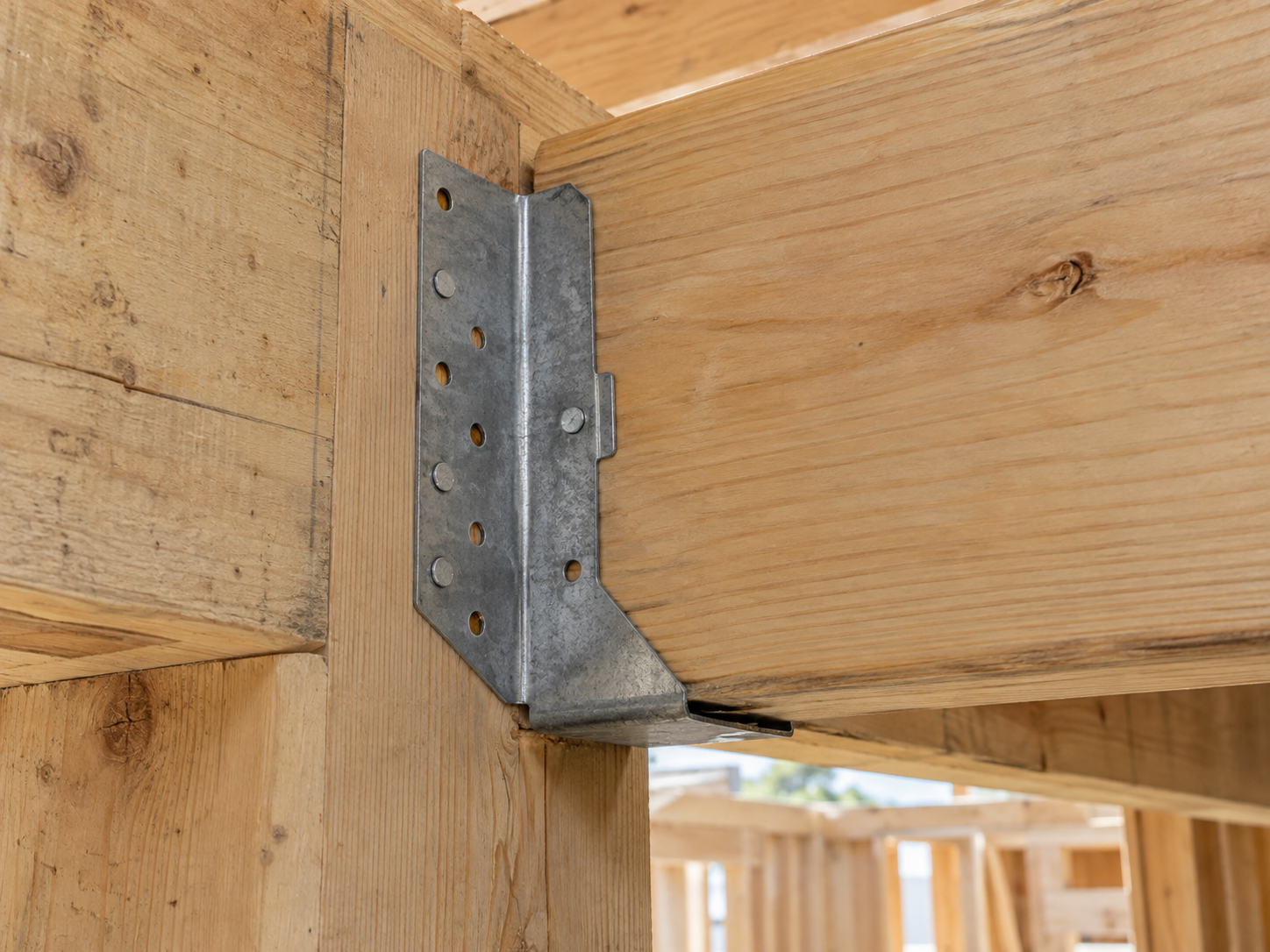 Visible unfilled holes in a joist connectorA galvanized metal hanger supports the end of a timber joist. Several round holes in the exposed flanges have no visible fasteners, while other holes contain fastener heads.Read picture report
 The connection has an inconsistent visible fastener pattern that warrants checking against the exact hanger model and approved framing detail. Empty holes alone do not prove incorrect installation: required holes, fastener type, length and pattern depend on the connector and design. The picture cannot establish embedment, concealed fasteners, bearing adequacy, design loads or structural capacity.
1. Identify the location on the framing plan and record the connector model before concealment. 2. Have the authorized reviewer compare the installed pattern with the approved design and manufacturer’s listed installation. 3. If a deficiency is confirmed, arrange a qualified installer and any necessary engineer-directed support before disturbing the connection. 4. Use only the specified connector fasteners and compatible replacement hardware; do not substitute general-purpose screws or assume every unused hole requires a nail. 5. Recheck the completed connection and document the approved disposition before the work is covered.
Record the model, approved detail, installed fastener specification, reviewer disposition and clear close-up and overview photos before concealment.
Applicable requirement: Confirm the selected state’s adopted building code, local amendments, permit edition, approved framing plans and the connector manufacturer’s installation requirements. The illustration does not establish a specific code violation or structural acceptance. An illustrative image does not establish a field measurement or compliance result.
 Torn weather barrier and lifted window flashingThe white weather-resistant wrap is torn beside the lower corner of the window, exposing brown sheathing. Black flashing at the corner appears wrinkled and lifted away from the surface.Read picture report
 The visible tear and loose flashing interrupt the apparent continuity of the exterior water-control layers at a sensitive window corner. This creates a condition needing review before cladding covers it. The picture does not reveal the concealed sill pan, drainage path, substrate moisture, adhesion strength or whether the installation is still in progress; it does not prove an active leak.
1. Mark the affected corner and review the approved window and weather-barrier detail before installing cladding. 2. Remove or rework damaged and loose material as directed by the product manufacturer and responsible building professional. 3. Prepare a clean, dry, suitable substrate and install compatible replacement wrap patches, flashing tape and specified primer or sealant in the correct drainage sequence. 4. Preserve required drainage openings; do not cover the defect with an arbitrary bead of sealant. 5. Verify adhesion, laps and continuity, perform any required field test, and obtain the required review before concealment.
Keep before-and-after images of sill, jamb and head transitions, product compatibility information, completed field checks and the reviewer’s release for concealment.
Applicable requirement: Apply the governing state/local adopted building or residential code, permit conditions and approved exterior-wall details together with the relevant product installation instructions. Verify required flashing and drainage details; no leak or compliance result is established from this image. An illustrative image does not establish a field measurement or compliance result.
 Open gap around a service penetrationA grey service passes through an oversized opening in a white board partition. A dark, irregular annular gap is visible between the service and cut edge, with no seal visible from this side.Read picture report
 The open perimeter needs comparison with the required partition assembly and construction stage. It may need an approved penetration treatment, but the image does not establish whether this partition is fire- or smoke-rated, the exact service type, assembly thickness, concealed treatment or the permitted opening size. An unsealed opening cannot be labeled a fire-code violation without that context.
1. Locate the penetration on the approved plans and establish the assembly rating and intended service. 2. Have the responsible trade and reviewer select the appropriate approved detail; where a rated assembly applies, identify a listed system matching the assembly, service and measured opening. 3. Prepare the opening and install the specified backing, sealant, collar or other system components only when that selected detail requires them. Do not use generic foam or caulk as an assumed firestop. 4. Follow the approved depth, support and installation requirements and complete the required inspection. 5. Photograph the completed work and retain the system/detail identification and reviewer disposition.
Record assembly and service identification, measured opening, approved detail or listed system, installed components and before-and-after evidence with the required review.
Applicable requirement: Verify the state/local adopted building and fire provisions, approved assembly and applicable tested/listed penetration system. A rating, required firestop system or compliance decision cannot be inferred from the photograph alone. An illustrative image does not establish a field measurement or compliance result.
All images and findings are illustrative. They show report structure and inspection topics, not actual field evidence or a compliance decision.
Detailed observations, location fields, practical recommendations and a standards assessment for every finding. Download your assessments as PDF reports with photos or Excel workbooks with picture links. Explore the three-row Excel examples below.
| Location / sample GPS | Potential finding | Recommended next step |
|---|---|---|
| Building example · Floor framing28.538300 -81.379200 | Visible unfilled holes in a joist connectorA galvanized metal hanger supports the end of a timber joist. Several round holes in the exposed flanges have no visible fasteners, while other holes contain fastener heads. | Verify the connector model and required fastener pattern before correcting the connection.Picture |
| Building example · Window corner28.538400 -81.379300 | Torn weather barrier and lifted window flashingThe white weather-resistant wrap is torn beside the lower corner of the window, exposing brown sheathing. Black flashing at the corner appears wrinkled and lifted away from the surface. | Restore the weather-barrier and flashing continuity using the approved window detail.Picture |
| Building example · Service penetration28.538500 -81.379400 | Open gap around a service penetrationA grey service passes through an oversized opening in a white board partition. A dark, irregular annular gap is visible between the service and cut edge, with no seal visible from this side. | Establish the partition rating and approved penetration detail, then treat the opening accordingly.Picture |
Building example · Floor framing · Fictional project location
Sample GPS: 28.538300, -81.379200
Confirm the selected state’s adopted building code, local amendments, permit edition, approved framing plans and the connector manufacturer’s installation requirements. The illustration does not establish a specific code violation or structural acceptance.
Building example · Window corner · Fictional project location
Sample GPS: 28.538400, -81.379300
Apply the governing state/local adopted building or residential code, permit conditions and approved exterior-wall details together with the relevant product installation instructions. Verify required flashing and drainage details; no leak or compliance result is established from this image.
Building example · Service penetration · Fictional project location
Sample GPS: 28.538500, -81.379400
Verify the state/local adopted building and fire provisions, approved assembly and applicable tested/listed penetration system. A rating, required firestop system or compliance decision cannot be inferred from the photograph alone.
Each finding links to its own illustrative picture, including Ai-generated demonstration scenes. Descriptions identify visible conditions; location labels and GPS are fictional examples. Field verification is required before deciding compliance or corrective work.
Connect the condition, supporting evidence and next action without losing the context.
Select the state and record the local authority, permit edition, construction stage and approved detail when known.
Review framing, envelope, service penetrations and other visible building components without substituting roadway criteria.
Keep required field checks, practical work steps, suitable materials and closeout evidence in the Excel report.
TruInspector supports documentation. It does not provide engineering design approval, construction acceptance, structural certification or a substitute for required professional services.
Review applicable sourcesTurn photos and recorded video into a reviewable condition record. Keep visible findings, evidence, recommended actions and follow-up together.
Share observations and supporting pictures in a report your team can review.
Keep category, condition, description and action notes organized. Include location and GPS when supported by the evidence.
Classify mixed photos, review separate asset reports and track work status in the Data Hub.