Now Compatible With All 50 States’ Standards and Regulations
Turn photos and video into clear reports.
TruInspector uses Ai to review photos and recorded videos, flag visible issues and match findings to state specific standards and requirements. Get PDF and photo-linked Excel reports to support compliance review and maintenance decisions.
Stay Ahead ofyour Inspections, Avoid Fines, Penalties and Have Full Control ofyour Project.
Detailed observations, location fields, practical recommendations and a standards assessment for every finding. Download your assessments as PDF reports with photos or Excel workbooks with picture links. Explore the three-row Excel examples below.
Home Inspections: three observations from the linked example pictures
Location / sample GPS
Potential finding
Recommended next step
Home · West roof slope27.950610 -82.457180
Missing shingles expose the roof underlaymentAn irregular patch of missing or torn shingles exposes dark underlayment, with uneven edges around the opening.
Have a qualified roofer check the exposed area and nearby shingles, then specify compatible repairs.Picture
Home · Bedroom window27.950628 -82.457162
An open frame-to-wall joint and staining below the sillSealant has separated beside the white window frame; an open gap and brown streaking are visible at the lower corner.
Inspect the joint, flashing and drainage paths; repair the verified defect with compatible materials.Picture
Home · Kitchen sink27.950619 -82.457151
Droplets at the drain trap and staining on the cabinet baseDroplets hang from the white drain assembly above a dark, wet-looking patch on the cabinet floor.
Have a plumber locate the leak, repair the affected connection and verify the cabinet has dried.Picture
Explore full findings, recommendations & standards
Missing shingles expose the roof underlayment
Fictional home · West roof slope above the garage · Illustrative location; GPS is sample data Sample GPS: 27.950610, -82.457180
What the picture shows
The center of the roof photograph shows an irregular area where gray shingle tabs are missing or torn away. Dark underlayment is visible through the opening. Several adjacent shingle edges appear lifted or uneven; the picture does not show the underside of the roof.
Detailed finding
The roof covering is visibly interrupted and the underlying layer is exposed. This creates a potential route for weather intrusion and further deterioration at the edges. The photograph cannot establish the age of the damage, the cause, the condition of the roof deck or whether water has reached the interior. The extent of the repair must be established through safe access and an examination of adjoining materials.
What the inspector should look for
Measure the exposed area and inspect surrounding tabs and fastening from safe access.
Check underlayment, flashing and accessible deck condition; look for corresponding interior moisture evidence.
Confirm roof assembly, product compatibility, manufacturer instructions and the applicable local repair requirements.
Recommended action
1. Arrange safe assessment by a qualified roofing contractor; keep occupants away from any falling or loose material.
2. Map missing, torn and loose shingles and inspect adjoining underlayment, flashing and accessible deck condition. Check interior areas below for corroborating signs of moisture.
3. If needed, have the roofer provide suitable temporary weather protection while the permanent repair is planned.
4. Replace affected materials with compatible shingles, underlayment, fasteners and flashing components as required by the verified assembly and manufacturer instructions. Confirm local permit requirements and repair limits before work.
5. Photograph the completed repair and have the roofer verify continuity, fastening and weather-shedding details. Do not assume replacing visible tabs alone resolves concealed damage.
Closeout documentation
Keep before-and-after roof overviews and close-ups, measured repair limits, installed product details and the roofer's completion record. Record any interior moisture checks and unresolved inaccessible areas.
Standards assessment
Not determined — field verification required
ASHI includes roofing materials and flashing within a visual inspection scope. Confirm state requirements, contracted scope, local adopted rules and manufacturer instructions. The photograph alone cannot establish roof-system compliance.
An open frame-to-wall joint and staining below the sill
Fictional home · Rear bedroom window, lower-left exterior corner · Illustrative location; GPS is sample data Sample GPS: 27.950628, -82.457162
What the picture shows
At the lower-left window corner, the sealant line between the white frame and cream-colored stucco is cracked and separated. A dark opening is visible along the vertical joint. Stucco is chipped near the corner, and brown streaking runs down the finish below the sill.
Detailed finding
The visible gap interrupts the exterior weather seal and warrants investigation of possible moisture entry. Staining indicates a condition to trace, but the photograph does not establish an active leak, concealed decay, flashing failure or the condition of the interior wall. The joint and the intended window drainage paths need to be distinguished before any sealant is applied.
What the inspector should look for
Record joint dimensions, loose finish and the continuity of adjacent seals.
Identify drainage and weep openings; inspect accessible flashing and the corresponding interior surface.
Verify material compatibility and determine whether movement, installation or moisture issues require a broader repair.
Recommended action
1. Document the length and width of the separated joint and inspect the surrounding stucco and frame attachment.
2. Check sill drainage, weep openings and accessible flashing details; examine the interior and use appropriate moisture checks where warranted.
3. Identify the cause of separation before repair. Have a qualified contractor remove failed sealant and loose material and prepare sound, dry surfaces according to the selected product instructions.
4. Use compatible exterior sealant, correctly sized backer rod where required, and an appropriate stucco repair system after confirming the assembly. Keep designed drainage openings clear; do not simply cover the gap and weeps.
5. Recheck the repaired joint and drainage function, and document any agreed leak investigation or follow-up after rainfall.
Closeout documentation
Retain close-up photographs of the prepared and repaired joint, product and compatibility information, drainage checks and any moisture readings. Record remaining inaccessible areas and the follow-up plan.
Standards assessment
Not determined — field verification required
ASHI covers observable exterior wall coverings, flashing and trim. Verify the state inspection scope, local requirements and window-system instructions. A photograph does not prove the flashing or water-resistance performance.
Droplets at the drain trap and staining on the cabinet base
Fictional home · Kitchen sink cabinet, drain trap · Illustrative location; GPS is sample data Sample GPS: 27.950619, -82.457151
What the picture shows
The photograph shows hanging droplets near the white PVC trap assembly and slip-joint connection. A dark, wet-looking patch and staining are visible on the cabinet base below the drain. Speckled discoloration is present toward the rear surface; its composition is not identifiable from the image.
Detailed finding
The visible droplets and cabinet staining are consistent with a drain leak that needs confirmation during operation. Continued wetting could damage cabinet materials. The picture cannot identify the precise failed seal, prove a supply-line leak, determine moisture behind the cabinet or identify mold. The drain should be checked under controlled flow and the cabinet assessed separately for damage and moisture.
What the inspector should look for
Observe the source of leakage during a controlled drain test and check all visible connections.
Inspect cabinet material for deterioration and record moisture readings where appropriate.
1. Limit sink use if leakage continues and protect the cabinet while arranging a qualified plumbing assessment.
2. Run a controlled leak check and inspect the trap, slip-joint washers, alignment, cracks and connection seating. Do not assume tightening alone is an adequate repair.
3. Repair or replace the verified failed components using compatible trap fittings, correctly sized washers and approved connection materials. Confirm the plumbing configuration against applicable local requirements.
4. Dry affected surfaces, assess softened or damaged cabinet materials and determine whether further moisture investigation or specialist work is needed.
5. Repeat the flow test after repair and document dry connections and cabinet moisture checks before closing the issue.
Closeout documentation
Record the repaired connection and installed components, the completed leak test, before-and-after photos and cabinet moisture checks. Keep any remaining damage or specialist follow-up open.
Standards assessment
Not determined — field verification required
ASHI includes readily accessible interior drain, waste and vent systems. Confirm state scope and locally adopted plumbing requirements. Visible droplets support a leak concern but do not establish whole-system compliance.
Property Management & Restoration: three observations from the linked example pictures
Location / sample GPS
Potential finding
Recommended next step
Unit 204 · Entry door28.538340 -81.379220
A split jamb and incomplete strike-plate fasteningThe latch-side jamb is split around the strike plate, with exposed wood and an empty upper fastener hole.
Check that the door secures correctly and repair the damaged jamb and strike assembly.Picture
Unit 204 · Living room28.538352 -81.379207
Raised flooring seams along the walking routeWood-look floor boards have peaked seams and lifted edges; the picture does not establish the height or cause.
Measure the unevenness, investigate moisture and movement, and repair the affected flooring.Picture
Unit 204 · Bedroom ceiling28.538361 -81.379199
Broad ceiling staining and peeling finish above the windowTan discoloration spreads across the ceiling, with blistered and loose finish near the joint above the window.
Trace the moisture source, measure affected materials and document drying before repairing the finish.Picture
Explore full findings, recommendations & standards
A split jamb and incomplete strike-plate fastening
Fictional apartment community · Unit 204 entry, latch-side jamb · Illustrative location; GPS is sample data Sample GPS: 28.538340, -81.379220
What the picture shows
The white entry door is partly open. Its latch-side jamb has a vertical split around the strike plate and exposed raw wood above and below the hardware. The upper strike-plate fastener hole appears empty; a lower fastener remains visible.
Detailed finding
The strike plate is mounted against visibly damaged material, so reliable latch engagement and security require a functional check. The photo does not show the door closing or locking, establish the cause of damage, or identify a fire-rated assembly. Treat this as a property condition needing prompt verification rather than attributing damage to a resident or declaring a code violation.
What the inspector should look for
Test closing, latch engagement and lock operation; document any immediate security concern.
Inspect the split, fastening points, frame attachment, hinges and door alignment.
Check assembly labels and applicable property, local and program requirements before selecting replacement components.
Recommended action
1. Arrange a prompt maintenance check of closing, latching and locking, coordinating resident access and immediate security needs.
2. Inspect the full jamb, strike anchorage, door alignment, hinges and surrounding wall for the extent of damage.
3. Repair or replace damaged jamb material and fit compatible strike hardware and fasteners into sound supporting material under the verified assembly requirements. A cosmetic filler patch alone should not be assumed to restore hardware anchorage.
4. Check for labels and any fire or smoke rating before altering components; use an appropriately qualified contractor and compatible listed parts when a rated assembly is involved.
5. Verify normal opening, closing and locking after repair and record photographs and the resident or manager handover.
Closeout documentation
Record repaired frame and hardware photos, installed components, successful latch/lock function checks and manager acceptance. Document any applicable rating information and remaining limitations.
Standards assessment
Not determined — field verification required
Compare operation and security with owner requirements and applicable local rules. HUD NSPIRE is a reference only where the property is subject to that program. The photo does not establish door operation, anchorage strength or a compliance result.
Fictional apartment community · Unit 204 living-room walkway · Illustrative location; GPS is sample data Sample GPS: 28.538352, -81.379207
What the picture shows
Several seams in the wood-look flooring are visibly raised, with lifted board edges extending across the foreground toward the wall. Reflections and shadows emphasize the uneven joints. No standing water is visible in the photograph.
Detailed finding
The uneven floor surface may interfere with normal walking and needs a measured field review. The image does not quantify the change in level or establish water damage, installation error, subfloor condition or responsibility. A repair should address the verified cause of lifting rather than only press or fasten the visible edges back into place.
What the inspector should look for
Measure raised edges and document the affected area within the normal walking route.
Check moisture, movement clearances, board damage and accessible subfloor condition.
Confirm the floor system and manufacturer repair method, plus applicable property and local requirements.
Recommended action
1. Identify the affected walking route and manage access appropriately while the uneven surface is assessed.
2. Map raised seams and measure the maximum change in level. Check board condition, moisture, perimeter movement gaps and accessible subfloor conditions.
3. Compare observations with the flooring manufacturer's installation and service requirements, property maintenance criteria and applicable local rules.
4. Correct the confirmed cause, then use compatible replacement boards, underlayment and approved fastening or bonding materials where required by the system. Do not conceal unresolved moisture beneath new flooring.
5. Verify the repaired surface is stable and even under the applicable criteria and document moisture and dimensional checks.
Closeout documentation
Keep measured before-and-after levels, moisture readings where relevant, material details and matched photographs. Record the cause addressed, the final walking-surface check and manager acceptance.
Standards assessment
Not determined — field verification required
Apply owner maintenance criteria, relevant local rules and manufacturer instructions. HUD NSPIRE Floor criteria apply only to covered properties. No height threshold, cause or compliance outcome can be established from this perspective image.
Broad ceiling staining and peeling finish above the window
Fictional apartment community · Unit 204 bedroom ceiling above window · Illustrative location; GPS is sample data Sample GPS: 28.538361, -81.379199
What the picture shows
The ceiling above the window has broad pale-brown staining and areas of peeling or blistered finish. A loose strip of surface coating hangs near a joint. The photograph does not show the space above the ceiling or any moisture measurements.
Detailed finding
The staining and disrupted coating indicate a moisture-related condition that warrants investigation and restoration planning. The image cannot determine whether wetting is active, locate its source, identify mold or establish the structural condition of concealed materials. Repainting alone would not demonstrate that the source or affected materials have been adequately addressed.
What the inspector should look for
Trace the moisture source and determine whether wetting is active; review relevant history and adjacent areas.
Map measured moisture in affected and comparison materials and assess loose or deteriorated finishes.
Have the restoration lead verify the scope, drying criteria, contamination assessment and required specialist involvement.
Recommended action
1. Assess the area in person, manage access if material is loose, and identify whether the moisture source remains active.
2. Locate and correct the verified source through the appropriate trade. Record moisture readings across affected and comparison areas using suitable instruments, with the date, material and measurement location.
3. Have a qualified restoration lead assess material condition, contamination concerns and the required drying or removal scope. Do not infer contamination category from the photograph.
4. Select drying equipment and any replacement board, compatible patching materials, primer and finish only after the source, moisture condition and repair scope are verified. Follow the customer's approved restoration plan and applicable requirements.
5. Document the drying criteria and readings, complete authorized repairs, and retain before-and-after evidence and follow-up checks.
Closeout documentation
Keep the source-repair record, moisture map and drying logs, approved scope, material records and matching photographs. Separate observed improvement from verified completion, and document unresolved inaccessible areas.
Standards assessment
Not determined — field verification required
EPA guidance emphasizes correcting moisture sources and drying affected materials. Verify measurements, material condition, the customer's restoration plan and applicable requirements before specifying work. The photograph cannot establish mold, dryness or remediation completion.
Highway pavement: three observations from the linked example pictures
Location / sample GPS
Potential finding
Recommended next step
I-95 example · Cracked surface26.715300 -80.086800
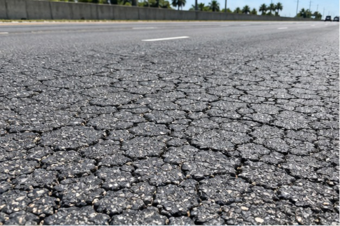
Interconnected cracking across the asphaltConnected cracks split the foreground asphalt into small pieces with chipped edges and open joints.
Measure the cracked area and check movement before choosing sealing or pavement repair.Picture
I-95 example · Damaged pavement edge26.716400 -80.086600
Broken asphalt and aggregate loss beside the edge lineDamaged pavement edge: a jagged strip of missing asphalt and loose aggregate follows the white edge line.
Measure the damaged strip and check edge support before selecting the repair.Picture
I-95 example · Eroded shoulder26.717500 -80.086400
Exposed pavement edge above an eroded shoulderEroded shoulder: soil loss exposes the asphalt edge and creates an abrupt, uneven shoulder transition.
Measure the edge drop and investigate support and erosion before restoring the transition.Picture
Explore full findings, recommendations & standards
Interconnected cracking across the asphalt
I-95 example · Cracked surface · Illustrative location; see the picture for the observation area Sample GPS: 26.715300, -80.086800
What the picture shows
A dense network of connected cracks divides the foreground asphalt into small, irregular pieces. Several crack edges are chipped, and open gaps are visible between the pieces.
Detailed finding
The linked close-up shows interconnected cracking across most of the foreground. Cracks intersect in several directions and isolate small blocks of asphalt, with chipped edges and dark, open joints. The cracking becomes less distinct toward the distant lane markings. This is visible surface deterioration that could admit water and continue breaking up under traffic. The picture does not establish crack depth, movement, pavement thickness, the cause of distress or the condition of the base.
What the inspector should look for
Measure the continuous cracked area and representative crack widths.
Check movement, loose edges, drainage and previous repairs.
Confirm the pavement construction and governing repair specification.
Recommended action
1. Mark the continuous cracked area during a protected field review and measure its extent and representative crack widths.
2. Check whether the pieces move under loading and examine drainage, patch history and the adjoining pavement.
3. Have the pavement lead distinguish stable surface cracking from failed pavement requiring removal and repair. Select treatment under the applicable agency specification; crack sealing alone may be unsuitable where the pavement is breaking apart.
4. Confirm the repair limits and compatible materials before work.
5. Record the completed treatment, surface condition and matching close-up and overview photographs.
Closeout documentation
Record measured repair limits, selected treatment and materials. Retain matching overview and close-up photographs and the pavement lead’s acceptance check.
Standards assessment
Not determined — field verification required
FDOT pavement-condition guidance considers cracking extent and severity. A single perspective image cannot establish a route-level pavement rating or contract acceptance. Measure affected area and crack widths, confirm the applicable contract and assess the full segment before assigning a result.
Broken asphalt and aggregate loss beside the edge line
I-95 example · Damaged pavement edge · Illustrative location; see the picture for the observation area Sample GPS: 26.716400, -80.086600
What the picture shows
In the linked picture, a rough, broken strip runs beside the white edge line. Missing asphalt leaves irregular cavities and loose aggregate along the shoulder-side edge.
Detailed finding
The picture shows a continuous-looking band of damaged asphalt immediately outside the white edge line. Its boundary is jagged, and stones and broken asphalt occupy the eroded strip. Loss of material is concentrated at the shoulder-side edge. Continued loss could reduce the sound paved width. The image does not establish the strip’s depth, measured length, maximum width or whether deeper support is affected.
What the inspector should look for
Locate the damaged strip beside the white edge line.
Measure width, depth and continuous length of asphalt loss.
Check edge support, adjacent pavement and runoff before selecting treatment.
Recommended action
1. Locate the damaged strip and measure its width, depth and continuous length under suitable traffic control.
2. Check loose material, the adjacent sound pavement and runoff at the shoulder transition.
3. Have the maintenance lead select repair limits that reach stable material and determine whether the support beneath the edge also needs correction.
4. Use compatible repair material and the agency-approved preparation and placement method.
5. Verify the restored edge, transition and drainage, and retain before-and-after photographs with measured limits.
Closeout documentation
Record the repaired length, width and treatment. Photograph the restored edge and verify the shoulder transition and drainage on site.
Standards assessment
Not determined — field verification required
Confirm the governing pavement-maintenance criteria and measure the affected edge. This picture supports an observation of edge deterioration but does not establish a segment rating or acceptance result.
I-95 example · Eroded shoulder · Illustrative location; see the picture for the observation area Sample GPS: 26.717500, -80.086400
What the picture shows
In the linked picture, the asphalt edge stands above a lowered, uneven soil shoulder. Soil loss has exposed the side of the pavement and left small recesses below parts of its edge.
Detailed finding
The picture shows a sharp asphalt boundary beside an eroded soil shoulder. The shoulder surface is lower and uneven, and the exposed pavement edge appears locally undercut. The concern is loss of support beside the pavement and an abrupt transition for a vehicle leaving the paved surface. The picture cannot determine the vertical drop, the depth of any undercut, the full affected length or the cause of the soil loss.
What the inspector should look for
Locate the exposed asphalt edge beside the lowered soil shoulder.
Measure the vertical transition, undercut and affected length.
Check drainage and pavement support before defining the repair.
Recommended action
1. Measure the edge drop and affected length from a protected work area.
2. Check the exposed pavement for unsupported sections and examine the shoulder drainage and signs of recurring erosion.
3. Have the maintenance lead establish how to restore support and the required shoulder profile without obstructing drainage.
4. Repair unsound pavement where confirmed and restore suitable shoulder material to the approved detail.
5. Check the finished transition and stability, record measurements and photograph the same edge before and after work.
Closeout documentation
Retain measured before-and-after edge levels, restored material and repair limits. Verify stability and drainage and photograph the complete repaired transition.
Standards assessment
Not determined — field verification required
Apply the responsible agency’s pavement-edge and shoulder criteria to measured field conditions. Image perspective cannot establish a drop-off threshold, support adequacy or a pass/fail result.
OSHA assessment: three observations from the linked example pictures
Location / sample GPS
Potential finding
Recommended next step
Site A example · Left of trench28.538300 -81.379200
Excavated soil piled close to an open trenchThe spoil mound sits close to the trench edge; falling or rolling material is a potential concern.
Measure the setback and have the competent person verify material retention and access.Picture
Site A example · Right trench edge28.538400 -81.379100
Heavy equipment positioned beside the trenchThe excavator’s wheels and blade sit close to the edge of an open, braced utility trench.
Verify edge clearance, ground support, operator visibility and worker separation.Picture
Site A example · Foreground crossing28.538500 -81.379000
Boards across the excavation need crossing verificationBoards span the foreground trench, but their suitability as a pedestrian crossing is unverified.
Confirm their use and verify a suitable crossing and required protective measures.Picture
Explore full findings, recommendations & standards
Excavated soil piled close to an open trench
Site A example · Left of trench · Illustrative location; see the picture for the observation area Sample GPS: 28.538300, -81.379200
What the picture shows
A large mound of excavated soil rises immediately beside the open trench on the left side of the picture. Loose soil extends toward the trench edge, creating a potential falling-material exposure.
Detailed finding
The left side of the linked construction photo contains a substantial spoil mound beside the open, braced trench. The toe of the mound approaches the excavation, and loose material is visible around the edge. Material could fall or roll into the excavation if workers are exposed. The photo does not establish the actual setback, the effectiveness of retaining measures, soil stability or whether anyone is working below.
What the inspector should look for
Measure spoil-to-edge setback.
Verify retaining measures and exposure below.
Have the competent person review the excavation and nearby material.
Recommended action
1. Have the site’s competent person review the spoil placement and worker exposure before allowing access below.
2. Measure the separation from the trench edge and check whether the visible support also provides suitable retention of loose material.
3. Relocate the spoil or provide the required retention under the site’s excavation plan. Keep workers out of the affected area while the arrangement is corrected.
4. Recheck the edge and protective system after the change.
5. Document the measured setback, controls and site review with an overview photograph.
Closeout documentation
Retain measured setback, the competent person’s review and photographs of the corrected spoil arrangement.
Standards assessment
Not determined — field verification required
29 CFR 1926.651(j)(2) addresses protection from materials or equipment falling or rolling into excavations. Measure setback and verify retaining measures and worker exposure before deciding compliance.
Site A example · Right trench edge · Illustrative location; see the picture for the observation area Sample GPS: 28.538400, -81.379100
What the picture shows
A wheeled excavator stands close beside an open, braced utility trench. Its wheels and front blade rest on the narrow strip of ground along the trench edge, while the bucket is held beyond the opening.
Detailed finding
The excavator occupies the ground immediately alongside the open trench. Its near-side wheels and blade are close to the edge, above the trench bracing and exposed utility pipe. Equipment loading could affect the ground at the edge, and planned movement may create equipment-to-edge or equipment-to-person conflicts. The still image does not establish whether the machine is moving, its measured clearance, the operator’s sight line, ground capacity or the adequacy of the excavation protection. Those conditions need an on-site review before deciding whether repositioning or additional controls are required.
What the inspector should look for
Measure equipment-to-edge clearance.
Confirm operator visibility and planned movements.
Review ground support and the applicable warning and separation arrangements.
Recommended action
1. Have the supervisor and competent person assess equipment positioning, planned movements and nearby worker access.
2. Measure the edge clearance and verify that the working surface and excavation arrangement suit the equipment loading.
3. Confirm the operator’s sight line and the warning or separation arrangements required for the actual operation.
4. Adjust the equipment position or access controls where the review identifies a conflict.
5. Record the approved arrangement, brief affected personnel and photograph the full operating area before work resumes.
Closeout documentation
Record the verified equipment arrangement, visibility review and controls, with photographs showing the machine, edge and worker route.
Standards assessment
Not determined — field verification required
29 CFR 1926.651(f) addresses warning systems when mobile equipment approaches an excavation without a clear operator view of the edge. Verify those conditions before applying the provision.
Boards across the excavation need crossing verification
Site A example · Foreground crossing · Illustrative location; see the picture for the observation area Sample GPS: 28.538500, -81.379000
What the picture shows
Several weathered timber planks form a narrow crossing over the open trench. The boards are uneven and separated by gaps, with rough, unprotected approaches at both ends.
Detailed finding
The planks bridge the excavation on short timber supports, with gaps between boards and an uneven walking surface. No side protection is visible, and loose soil and stones surround both approaches. If this is a designated crossing, its stability, width, load capacity and required protection need verification. The photograph cannot establish fastening, timber condition below the surface, measured height over the lower level or whether an approved alternative route is available.
What the inspector should look for
Confirm whether the boards are used for access.
Measure crossing dimensions and height and inspect support.
Verify the required protective arrangement and safe approaches.
Recommended action
1. Confirm whether workers or equipment are permitted to use the boards as a crossing.
2. If access is intended, have the competent person verify its construction, support, width, fastening and height before use.
3. Provide the required crossing and protective arrangements, or close this route and direct people to an approved alternative.
4. Remove trip conflicts from the approach as part of the access arrangement.
5. Record the verified crossing, access instructions and photographs showing both approaches and the excavation below.
Closeout documentation
Document the competent person’s crossing review, measurements and photographs of the complete approved route.
Standards assessment
Not determined — field verification required
29 CFR 1926.651(l) addresses crossings over excavations and protection at qualifying heights. Confirm intended use, measured height and the installed arrangement before determining compliance.
Building construction: three observations from the linked example pictures
Location / sample GPS
Potential finding
Recommended next step
Building example · Floor framing28.538300 -81.379200
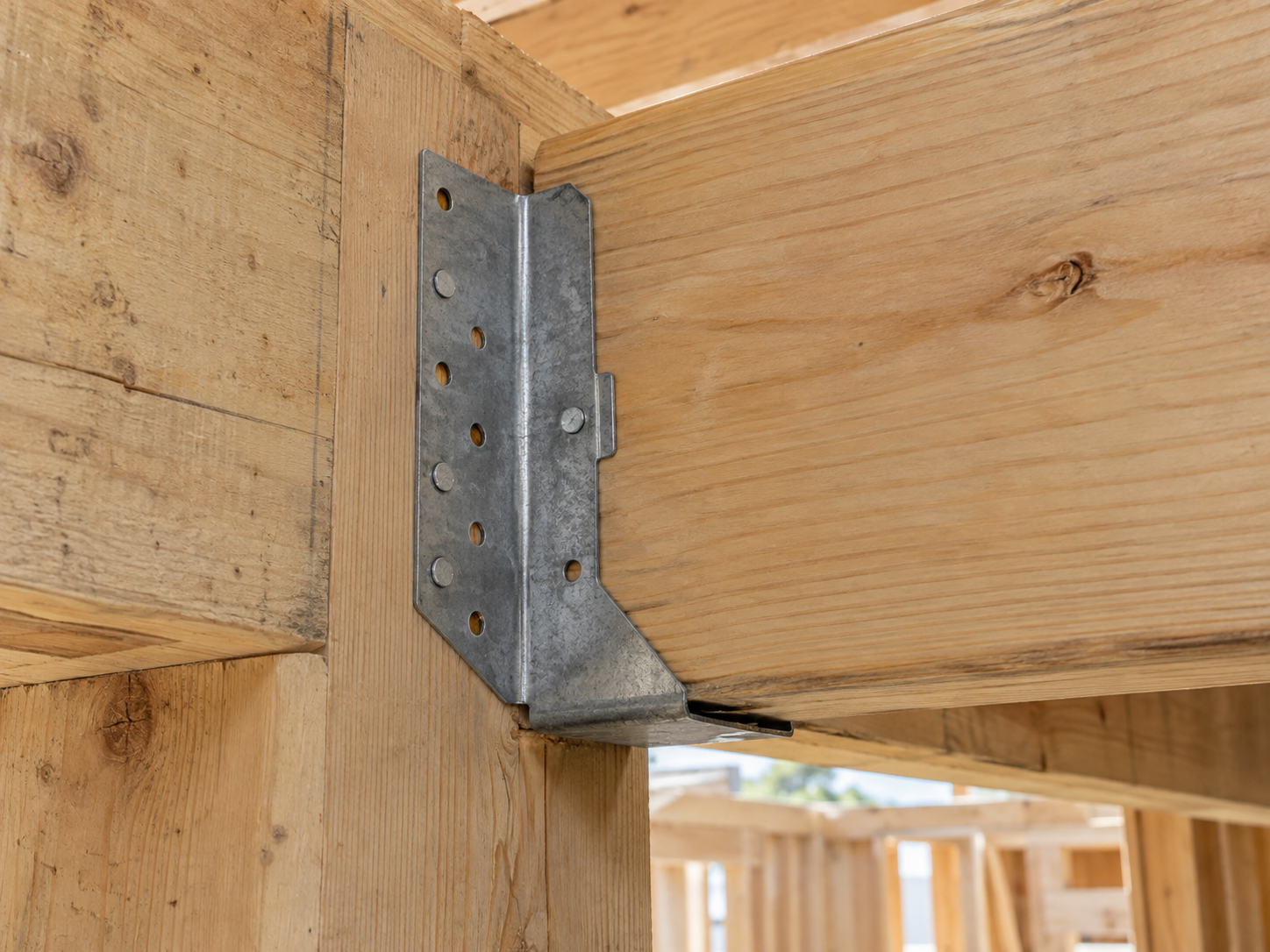
Visible unfilled holes in a joist connectorA galvanized metal hanger supports the end of a timber joist. Several round holes in the exposed flanges have no visible fasteners, while other holes contain fastener heads.
Verify the connector model and required fastener pattern before correcting the connection.Picture
Building example · Window corner28.538400 -81.379300
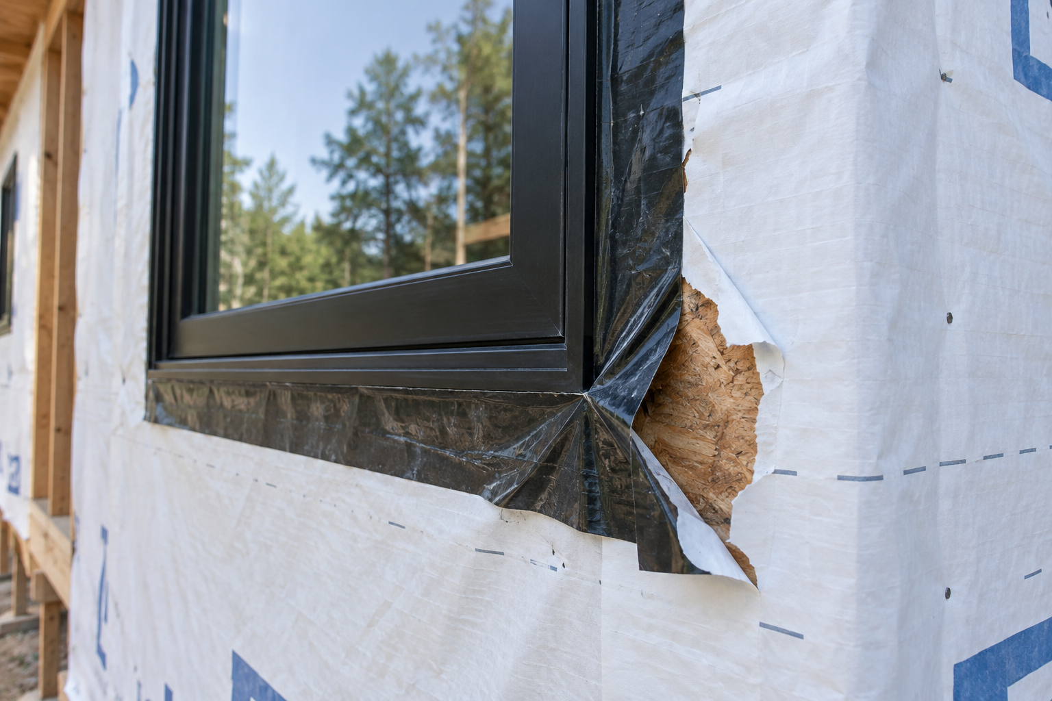
Torn weather barrier and lifted window flashingThe white weather-resistant wrap is torn beside the lower corner of the window, exposing brown sheathing. Black flashing at the corner appears wrinkled and lifted away from the surface.
Restore the weather-barrier and flashing continuity using the approved window detail.Picture
Building example · Service penetration28.538500 -81.379400
Open gap around a service penetrationA grey service passes through an oversized opening in a white board partition. A dark, irregular annular gap is visible between the service and cut edge, with no seal visible from this side.
Establish the partition rating and approved penetration detail, then treat the opening accordingly.Picture
Explore full findings, recommendations & standards
Visible unfilled holes in a joist connector
Building example · Floor framing · Fictional project location Sample GPS: 28.538300, -81.379200
What the picture shows
A galvanized metal hanger supports the end of a timber joist. Several round holes in the exposed flanges have no visible fasteners, while other holes contain fastener heads.
Detailed finding
The connection has an inconsistent visible fastener pattern that warrants checking against the exact hanger model and approved framing detail. Empty holes alone do not prove incorrect installation: required holes, fastener type, length and pattern depend on the connector and design. The picture cannot establish embedment, concealed fasteners, bearing adequacy, design loads or structural capacity.
What the inspector should look for
Identify the connector model, approved framing detail and manufacturer’s required fastener schedule.
Compare required holes with installed fasteners; verify type, diameter, length and compatible materials.
Check bearing, timber condition and any split or damaged connection with the responsible building professional.
Recommended action
1. Identify the location on the framing plan and record the connector model before concealment.
2. Have the authorized reviewer compare the installed pattern with the approved design and manufacturer’s listed installation.
3. If a deficiency is confirmed, arrange a qualified installer and any necessary engineer-directed support before disturbing the connection.
4. Use only the specified connector fasteners and compatible replacement hardware; do not substitute general-purpose screws or assume every unused hole requires a nail.
5. Recheck the completed connection and document the approved disposition before the work is covered.
Closeout documentation
Record the model, approved detail, installed fastener specification, reviewer disposition and clear close-up and overview photos before concealment.
Standards assessment
Not determined — adopted requirements and field verification required
Confirm the selected state’s adopted building code, local amendments, permit edition, approved framing plans and the connector manufacturer’s installation requirements. The illustration does not establish a specific code violation or structural acceptance.
Reference
Applicable state/local adopted building requirements, approved plans and product instructions
Torn weather barrier and lifted window flashing
Building example · Window corner · Fictional project location Sample GPS: 28.538400, -81.379300
What the picture shows
The white weather-resistant wrap is torn beside the lower corner of the window, exposing brown sheathing. Black flashing at the corner appears wrinkled and lifted away from the surface.
Detailed finding
The visible tear and loose flashing interrupt the apparent continuity of the exterior water-control layers at a sensitive window corner. This creates a condition needing review before cladding covers it. The picture does not reveal the concealed sill pan, drainage path, substrate moisture, adhesion strength or whether the installation is still in progress; it does not prove an active leak.
What the inspector should look for
Confirm installation stage, approved window detail and compatibility of the wrap, tape, primer and sealants.
Inspect the full sill, jamb and head sequence, overlaps, adhesion and intended drainage openings.
Check substrate condition and any moisture through appropriate field methods before closing the assembly.
Recommended action
1. Mark the affected corner and review the approved window and weather-barrier detail before installing cladding.
2. Remove or rework damaged and loose material as directed by the product manufacturer and responsible building professional.
3. Prepare a clean, dry, suitable substrate and install compatible replacement wrap patches, flashing tape and specified primer or sealant in the correct drainage sequence.
4. Preserve required drainage openings; do not cover the defect with an arbitrary bead of sealant.
5. Verify adhesion, laps and continuity, perform any required field test, and obtain the required review before concealment.
Closeout documentation
Keep before-and-after images of sill, jamb and head transitions, product compatibility information, completed field checks and the reviewer’s release for concealment.
Standards assessment
Not determined — adopted requirements and field verification required
Apply the governing state/local adopted building or residential code, permit conditions and approved exterior-wall details together with the relevant product installation instructions. Verify required flashing and drainage details; no leak or compliance result is established from this image.
Reference
Applicable state/local adopted building requirements, approved plans and product instructions
Open gap around a service penetration
Building example · Service penetration · Fictional project location Sample GPS: 28.538500, -81.379400
What the picture shows
A grey service passes through an oversized opening in a white board partition. A dark, irregular annular gap is visible between the service and cut edge, with no seal visible from this side.
Detailed finding
The open perimeter needs comparison with the required partition assembly and construction stage. It may need an approved penetration treatment, but the image does not establish whether this partition is fire- or smoke-rated, the exact service type, assembly thickness, concealed treatment or the permitted opening size. An unsealed opening cannot be labeled a fire-code violation without that context.
What the inspector should look for
Confirm the partition’s required rating, approved assembly and the purpose and material of the service.
Measure the opening and annular space and compare with the applicable listed system or approved nonrated detail.
Check both accessible sides, support, installation stage and required inspection before concealment.
Recommended action
1. Locate the penetration on the approved plans and establish the assembly rating and intended service.
2. Have the responsible trade and reviewer select the appropriate approved detail; where a rated assembly applies, identify a listed system matching the assembly, service and measured opening.
3. Prepare the opening and install the specified backing, sealant, collar or other system components only when that selected detail requires them. Do not use generic foam or caulk as an assumed firestop.
4. Follow the approved depth, support and installation requirements and complete the required inspection.
5. Photograph the completed work and retain the system/detail identification and reviewer disposition.
Closeout documentation
Record assembly and service identification, measured opening, approved detail or listed system, installed components and before-and-after evidence with the required review.
Standards assessment
Not determined — adopted requirements and field verification required
Verify the state/local adopted building and fire provisions, approved assembly and applicable tested/listed penetration system. A rating, required firestop system or compliance decision cannot be inferred from the photograph alone.
Reference
Applicable state/local adopted building requirements, approved plans and product instructions
Landscaping: three observations from the linked example pictures
Location / sample GPS
Potential finding
Recommended next step
Site C example · Foreground lawn30.332200 -81.655700
Pale, browned turf across the foregroundThe foreground turf is yellow-brown while the lawn farther left is greener.
Check species, moisture and irrigation and distinguish dormancy from damage.Picture
Site C example · Right planting border30.332300 -81.655600
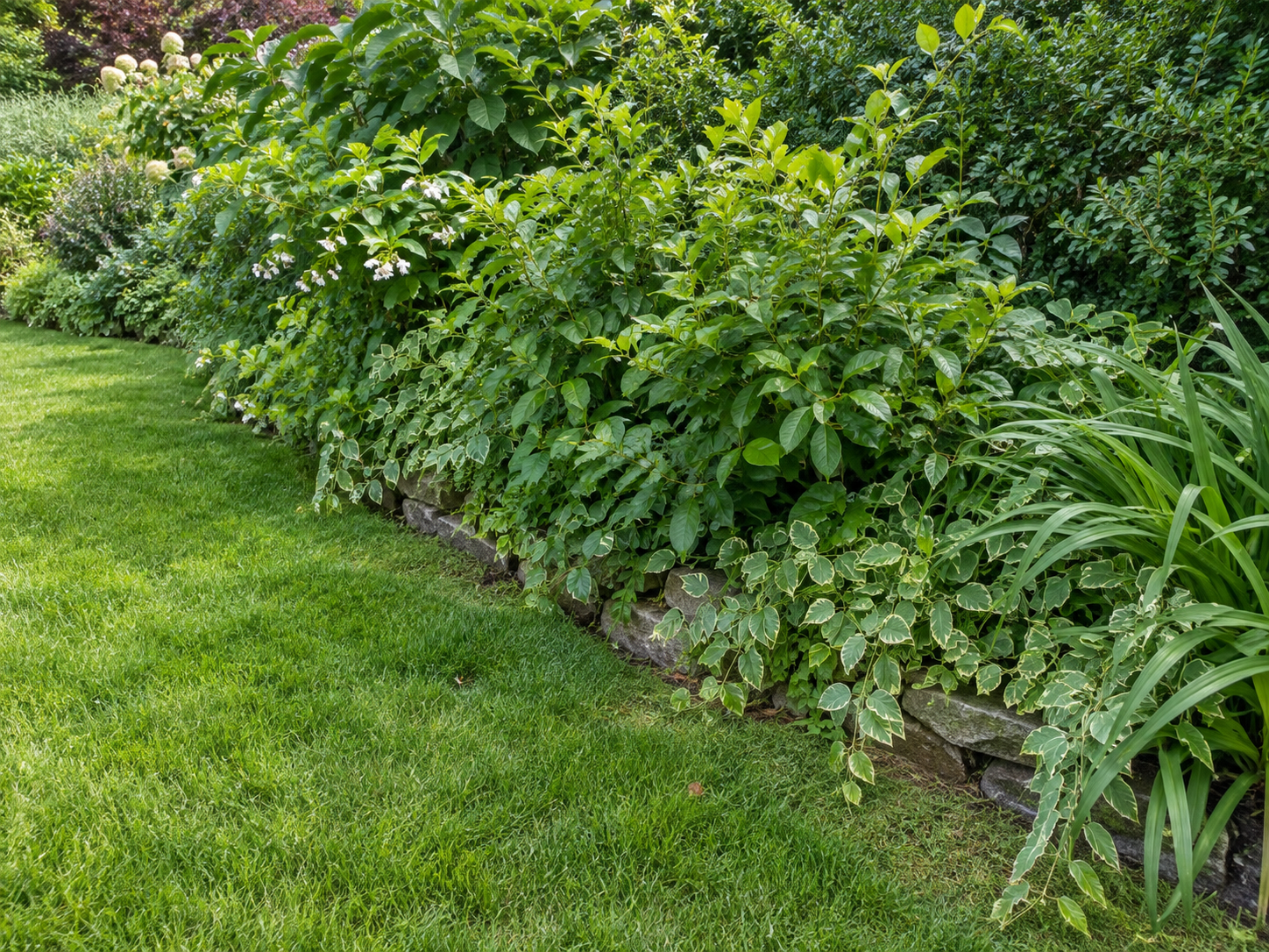
Plant growth obscures sections of the bed edgeFoliage covers sections of the stone bed edge; confirm whether the spread exceeds the intended planting line.
Compare with the planting plan and selectively shape only confirmed excess growth.Picture
Site C example · Roadside tree30.332400 -81.655500
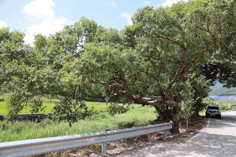
Large tree limb extends across the roadside vergeA large horizontal limb and hanging foliage sit close to the roadside access area.
Measure clearance and have an arborist define appropriate pruning work.Picture
Explore full findings, recommendations & standards
Pale, browned turf across the foreground
Site C example · Foreground lawn · Illustrative location; see the picture for the observation area Sample GPS: 30.332200, -81.655700
What the picture shows
The foreground lawn is pale yellow-brown and noticeably less green than the grass farther back on the left. The difference in turf color extends across a broad area near the planting border.
Detailed finding
A broad area of foreground turf is pale and brown compared with greener lawn near the planting border and left background. The color change is visible, but the plants in the border remain predominantly green. Turf stress or seasonal dormancy are possible explanations; the picture cannot distinguish them or prove dead grass. Species, soil moisture, weather history, irrigation coverage and root condition need field verification before treatment.
What the inspector should look for
Compare the foreground turf with the greener lawn.
Check species, moisture, weather and irrigation coverage.
Confirm dormancy or damage before prescribing treatment.
Recommended action
1. Map the discolored area and identify the turf species and recent weather and maintenance history.
2. Compare soil moisture and irrigation coverage in the pale and greener areas without assuming a watering fault.
3. Have the landscape lead check whether the turf is dormant, stressed or damaged and seek qualified diagnosis where needed.
4. Apply only the corrective treatment supported by that diagnosis and local water-use requirements.
5. Record observations and repeat photographs from the same position to assess recovery before deciding on replacement.
Closeout documentation
Retain the diagnosis, affected area, corrective action and matching follow-up photos documenting recovery or verified replacement needs.
Standards assessment
Not determined — field verification required
UF/IFAS notes that turf can brown during drought and later recover. Color alone does not establish dead grass or a contract failure. Compare verified turf condition with the project’s maintenance requirements.
Site C example · Right planting border · Illustrative location; see the picture for the observation area Sample GPS: 30.332300, -81.655600
What the picture shows
Dense foliage extends over portions of the stone-edged planting border on the right. The border line is partly concealed where the plants meet the lawn.
Detailed finding
The right-hand planting bed has a dense, irregular edge, with foliage covering sections of the low stone border and extending toward the lawn. This is a visible maintenance-review point if the approved design requires a defined bed boundary or clearance. It may also be an intentional planting form. The photograph does not show bare mulch patches, missing plants or an established access obstruction.
What the inspector should look for
Locate concealed sections of the stone bed boundary.
Compare plant spread with the approved design.
Identify plants and suitable pruning limits before work.
Recommended action
1. Compare the planted edge with the approved landscape design and required bed limits.
2. Identify which plants extend beyond the intended boundary and check their condition and suitable pruning season.
3. If the growth conflicts with the specification, have the landscape lead select limited shaping consistent with plant health. Avoid removing growth solely to match an assumed outline.
4. Retain the intended planting coverage and check the border after work.
5. Record the approved scope and matching photographs showing the restored boundary.
Closeout documentation
Record the approved shaping scope and matching before-and-after photographs of the bed boundary. Note retained plants and follow-up checks.
Standards assessment
Not determined — field verification required
UF/IFAS describes selective shrub pruning to maintain desired form. The project’s planting plan determines whether this spread needs correction; the image does not establish noncompliance.
Site C example · Roadside tree · Illustrative location; see the picture for the observation area Sample GPS: 30.332400, -81.655500
What the picture shows
A thick, low limb extends horizontally from the roadside tree over the grassy verge. Foliage also hangs toward the narrow road beside the trunk.
Detailed finding
The linked tree photo shows a substantial horizontal limb extending left across the verge, while the trunk and canopy stand close to the road on the right. Hanging foliage narrows the visible envelope near the roadway. The photograph supports a clearance review but does not prove that the limb blocks vehicles or that the tree is unstable. Required vehicle clearance, measured branch height, ownership, utility proximity and tree condition remain unverified.
What the inspector should look for
Measure the limb and foliage clearance from the actual road or access envelope.
Confirm ownership, utility proximity and required vehicle clearance.
Have a qualified arborist assess the limb before selecting pruning.
Recommended action
Measure clearance and confirm the facility's required access envelope. Have a qualified arborist assess the branch and select pruning consistent with tree health and permit requirements. Control access where contact is possible and coordinate utility involvement when relevant. After work, retain measured clearance, matched photographs and the approved pruning scope in the project record.
Closeout documentation
Record measured clearance, the approved arborist scope and matching photographs. Retain any follow-up tree-health review.
Standards assessment
Not determined — field verification required
UF/IFAS tree-care guidance supports selective pruning for clearance and appropriate arborist involvement. It does not establish a universal facility-access height. Obtain the local or project requirement, measure the route and confirm permissions. Document that comparison before deciding whether the condition meets the requirement.
Each finding links to its own illustrative picture, including Ai-generated demonstration scenes. Descriptions identify visible conditions; location labels and GPS are fictional examples. Field verification is required before deciding compliance or corrective work.
START HERE
See your first assessment, start to finish.
6 steps · About 45 seconds
TruInspector workspace · Sample data
STEP 1 OF 6
Start with your project
Open Evaluations. Enter the project location and choose your state, industry and assessment type. The assessment options follow the sector you select.
Type your roadway and direction. Use Other under Reference focus for a different requirement.
Read-only views of the TruInspector interface with illustrative findings. Plays when in view; pause or expand any step. Ai results and compliance conclusions require review.
Built Around your Work
your industry. your state’s references.
Explore roadway maintenance, public works, paving, drainage and other supported workflows. Find official DOT resources for all 50 states, plus OSHA references, with source-linked research and professional review.
Filter, reopen and manage saved assessment records.
Illustrative workspace previews use fictional records and no live customer data.
Evidence your Team Can Use
From an observation to an action.
Capture → analyze → review → export. Give reviewers the condition, supporting images, location and recommended work in one clear, traceable maintenance record.
Save, filter and reopen assessments in the Data Hub.
Track findings and work status in the dashboard.
Download PDF reports with embedded photos and Excel workbooks with picture links.
Include the defect, description, confidence, assessment result, supported GPS and recommended action.
Connect reviewers tothe images with up to four evidence-photo links.
Classify mixed photos, review the findings and export separate category reports.